PSU from a high-power energy-saving lamp. Switching power supply from an energy-saving lamp. Input filter capacitance and voltage ripple
Many thanks to the manufacturers of modern energy-saving lamps. The quality of their products constantly makes us think and pushes us to new technical solutions.
This time we will consider the topic of converting a failed energy-saving lamp into an LED one. Today we'll go the more traditional route using an LED driver, but... The most interesting part of the conversion is the LED itself.
The other day I came across several samples of the Chinese electronics industry. These LEDs themselves are interesting, although they do not have outstanding characteristics. But the fact that this LED provides a circular radiation pattern takes it to a whole new level and gives us an excellent tool for modernizing lighting systems.

As a radiator, I used the aluminum universal profile AP888, already known from the previous article, produced by Yug-Service LLC. Unfortunately, I only had a piece of it a little over 10mm thick. There was a fear that the power of 9 W might not be enough for an LED. But the desire to conduct an experiment won out.
A small drawback of this profile in relation to the new LED is that the central hole is 8 mm in diameter, and the thread of the “tail” of the LED is M6.
The easiest way out:
- drill the hole to 10 mm;
- screw the bolt into the M6 nut;
- carefully, hitting the head of the bolt with a hammer, press the nut into the profile. The bolt is needed so as not to accidentally jam the threads in the nut.


LED 7V, power 7-9 W, 12 V, 600-800 mA. As a driver, I used a widely used 700 mA driver for three LEDs from the same Chinese manufacturer.
Then, as always, everything is simple. We know how to disassemble an energy-saving light bulb, the main thing is not to break the bulb. And we prepare the entire kit for assembly.

1. Drill holes in the cover of the base housing to attach the radiator and wires.

2. Solder the positive wire of the driver to the central contact of the LED. Don't forget to first thread it through the radiator and the base cover.

3. Apply heat-conducting paste (KTP-8) to the thread of the LED and screw it into place. We attach the cover of the base housing to the radiator.


4. The negative wire of the driver must be connected to the radiator.

5. Solder the driver network wires into the base.

6. Collect everything into one.

7. The upgraded lamp is ready for use.


As for my concerns about the LED overheating due to the insufficient heatsink size, we can say that they turned out to be groundless. The temperature at the “LED-radiator” point after several hours of operation stopped at around 59-62 ºС (ambient temperature 23 ºС). In principle, this is acceptable, but if the radiator is increased by 5-10 mm, then you don’t have to worry about anything at all.
Everything is simple, beautiful and most importantly – accessible and not expensive.
Energy-saving light bulbs are widely used for both domestic and industrial purposes. Over time, any lamp becomes faulty. However, if desired, the lamp can be revived by assembling a power supply from an energy-saving lamp. In this case, the filling of a failed light bulb is used as components of the block.
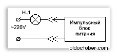
Pulse block and its purpose
At both ends of the fluorescent lamp tube there are electrodes, an anode and a cathode. Applying power causes the lamp components to heat up. After heating, electrons are released, which collide with mercury molecules. The consequence of this is ultraviolet radiation.

Due to the presence of phosphor in the tube, the phosphor is converted into the visible glow of the light bulb. The light does not appear immediately, but after a certain period of time after connecting to the power supply. The more worn out the lamp is, the longer the interval.
The operation of a switching power supply is based on the following principles:
- Converting alternating current from the electrical network to direct current. In this case, the voltage does not change (that is, it remains 220 V).
- Transformation of DC voltage into rectangular pulses due to the operation of a width pulse converter. The pulse frequency ranges from 20 to 40 kHz.
- Supplying voltage to the lamp using a choke.

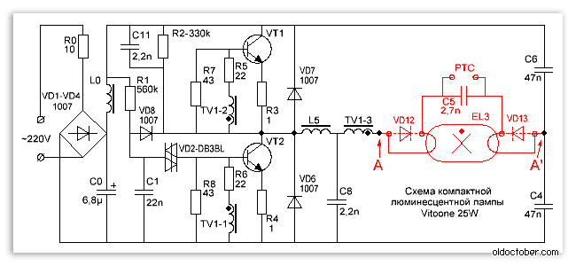
An uninterruptible power supply (UPS) consists of a number of components, each of which has its own marking in the diagram:
- R0 - plays a limiting and protective role in the power supply. The device prevents and stabilizes excessive current flowing through the diodes at the time of connection.
- VD1, VD2, VD3, VD4 - act as bridge rectifiers.
- L0, C0 - are filters for the transmission of electric current and protect against voltage surges.
- R1, C1, VD8 and VD2 - represent a chain of converters used during startup. The first resistor (R1) is used to charge capacitor C1. As soon as the capacitor breaks through the dinistor (VD2), it and the transistor open, resulting in self-oscillation in the circuit. Next, a rectangular pulse is sent to the diode cathode (VD8). A negative indicator appears, covering the second dinistor.
- R2, C11, C8 - facilitate the start of operation of the converters.
- R7, R8 - optimize the closing of transistors.
- R6, R5 - form boundaries for electric current on transistors.
- R4, R3 - are used as fuses during voltage surges in transistors.
- VD7 VD6 - protect power supply transistors from return current.
- TV1 is a reverse communication transformer.
- L5 - ballast choke.
- C4, C6 - act as isolation capacitors. Divide all the tension into two parts.
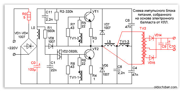
- TV2 is a pulse type transformer.
- VD14, VD15 - pulse diodes.
- C9, C10 - filter capacitors.
Note! In the diagram below, the components that need to be removed when remaking the block are marked in red. Points A-A are connected by a jumper.
Only a thoughtful selection of individual elements and their correct installation will allow you to create an efficiently and reliably operating power supply.
Differences between a lamp and a pulse unit
The circuit of the energy-saving lamp is in many ways similar to the structure of a switching power supply. That is why it is not difficult to make a switching power supply. To remake the device, you will need a jumper and an additional transformer that will issue pulses. The transformer must have a rectifier.
To make the power supply lighter, the glass fluorescent bulb is removed. The power parameter is limited by the highest throughput of the transistors and the size of the cooling elements. To increase power, it is necessary to wind additional winding on the inductor.

Modification of the block
Before you start remaking the power supply, you need to select the current output power. The degree of modernization of the system depends on this indicator. If the power is in the range of 20-30 W, there will be no need for deep changes in the circuit. If the planned power is more than 50 W, a more systematic upgrade is needed.
Note! There will be a constant voltage at the output of the power supply. It is not possible to obtain an alternating voltage at a frequency of 50 Hz.
Power determination
Power is calculated according to the formula:

As an example, consider the situation with a power supply having the following characteristics:
- voltage - 12 V;
- current strength - 2 A.
We calculate the power:
P = 2 × 12 = 24 W.
The final power parameter will be higher - approximately 26 W, which allows for possible overloads to be taken into account. Thus, to create a power supply, a fairly minor intervention in the circuit of a standard 25 W economy lamp will be required.
New components

New electronic components include:
- diode bridge VD14-VD17;
- 2 capacitors C9 and C10;
- winding on the ballast choke (L5), the number of turns of which is determined empirically.
The additional winding performs another important function - it is a separating transformer and protects against voltage penetration into the UPS outputs.
To calculate the required number of turns in the additional winding, perform the following steps:
- Temporarily apply a winding to the inductor (approximately 10 turns of wire).
- We connect the winding to the load resistance (power from 30 W and resistance 5-6 Ohms).
- We connect to the network and measure the voltage at the load resistance.
- We divide the result obtained by the number of turns and find out how many volts there are for each turn.
- We find out the required number of turns for a permanent winding.
The calculation procedure is shown in more detail below.
To calculate the required number of turns, divide the planned voltage for the block by the voltage of one turn. The result is the number of turns. It is recommended to add 5-10% to the final result, which will allow you to have a certain margin.

Do not forget that the original inductor winding is under mains voltage. If you need to wind a new layer of winding on it, take care of the inter-winding insulating layer. It is especially important to observe this rule when PEL type wire in enamel insulation is applied. Polytetrafluoroethylene tape (0.2 mm thick) is suitable as an interwinding insulating layer, which will increase the density of threaded connections. This type of tape is used by plumbers.
Note! The power in the block is limited by the overall power of the transformer involved, as well as the maximum possible current of the transistors.
Making your own power supply
You can make a UPS yourself. This will require minor modifications to the electronic throttle jumper. Next, the connection is made to the pulse transformer and rectifier. Individual elements of the scheme are removed due to their unnecessary use.
If the power supply is not too high-power (up to 20 W), it is not necessary to install a transformer. A few turns of conductor wound around a magnetic circuit located on the ballast of the light bulb is enough. However, this operation can only be carried out if there is sufficient space for the winding. For example, a conductor of the MGTF type with a fluoroplastic insulating layer is suitable for it.

Usually not much wire is needed, since almost the entire lumen of the magnetic circuit is given over to the insulation. It is this factor that limits the power of such blocks. To increase power you will need a pulse type transformer.
A distinctive characteristic of this type of SMPS (switching power supply) is the ability to adapt it to the characteristics of the transformer. In addition, the system does not have a feedback loop. The connection diagram is such that there is no need for particularly accurate calculations of the transformer parameters. Even if a gross error is made in the calculations, the uninterruptible power supply will most likely function.
A pulse transformer is created on the basis of a choke, on which a secondary winding is superimposed. As such, varnished copper wire is used.
The interwinding insulating layer is most often made of paper. In some cases, a synthetic film is applied to the winding. However, even in this case, you should additionally protect yourself and wrap 3-4 layers of special electrical protective cardboard. As a last resort, paper with a thickness of 0.1 millimeter or more is used. Copper wire is applied only after this safety measure has been provided.
![]()
As for the diameter of the conductor, it should be as large as possible. The number of turns in the secondary winding is small, so the appropriate diameter is usually selected by trial and error.
Rectifier
To prevent saturation of the magnetic circuit in the uninterruptible power supply, only full-wave output rectifiers are used. For a pulse transformer operating to reduce voltage, a circuit with a zero mark is considered optimal. However, for it it is necessary to make two absolutely symmetrical secondary windings.
For a switching uninterruptible power supply, a conventional rectifier operating according to a diode bridge circuit (using silicon diodes) is not suitable. The fact is that for every 100 W of transported power, the losses will be at least 32 W. If you make a rectifier from powerful pulsed diodes, the costs will be high.
Setting up an uninterruptible power supply
When the power supply is assembled, all that remains is to connect it to the largest load to check whether the transistors and transformer are overheating. The maximum temperature for the transformer is 65 degrees, and for transistors - 40 degrees. If the transformer gets too hot, you need to take a conductor with a larger cross-section or increase the overall power of the magnetic circuit.

The above actions can be performed simultaneously. For transformers made from choke balances, it will most likely not be possible to increase the cross-section of the conductor. In this case, the only option is to reduce the load.
High Power UPS
In some cases, the standard ballast power is not enough. As an example, let's take the following situation: you have a 24 W lamp and you need a UPS for charging with characteristics of 12 V/8 A.
To implement the scheme, you will need an unused computer power supply. From the block we take out the power transformer along with the R4C8 circuit. This circuit protects the power transistors from excessive voltage. We connect the power transformer to the electronic ballast. In this situation, the transformer replaces the inductor. Below is a diagram for assembling an uninterruptible power supply based on an energy-saving light bulb.

It is known from practice that this type of block makes it possible to receive up to 45 W of power. The heating of the transistors is within the normal range, not exceeding 50 degrees. To completely eliminate overheating, it is recommended to install a transformer with a large core cross-section into the transistor bases. Transistors are placed directly on the radiator.
Potential Bugs
There is no point in simplifying the circuit by applying the base windings directly to the power transformer. If there is no load, considerable losses will occur, since a large current will flow into the transistor bases.
If a transformer is used with an increase in load current, the current in the transistor bases will also increase. It has been empirically established that after the load reaches 75 W, saturation occurs in the magnetic circuit. The result of this is a decrease in the quality of the transistors and their excessive heating. To prevent such developments, it is recommended to wind the transformer yourself using a larger core cross-section. It is also possible to fold two rings together. Another option is to use a larger conductor diameter.
![]()
The base transformer, which acts as an intermediate link, can be removed from the circuit. For this purpose, the current transformer is connected to a dedicated winding of the power transformer. This is done using a high-power resistor based on a feedback circuit. The disadvantage of this approach is the constant operation of the current transformer under saturation conditions.
It is unacceptable to connect the transformer together with the choke (located in the ballast converter). Otherwise, due to the decrease in overall inductance, the frequency of the UPS will increase. The consequence of this will be losses in the transformer and excessive heating of the rectifier transistor at the output.
We must not forget about the high responsiveness of diodes to increased reverse voltage and current. For example, if you put a 6-volt diode in a 12-volt circuit, this element will quickly become unusable.

Transistors and diodes should not be replaced with low-quality electronic components. The performance characteristics of the Russian-made element base leave much to be desired, and the replacement will result in a decrease in the functionality of the uninterruptible power supply.
While scientists are taming the speed of light, I decided to tame unnecessary fluorescent lamps by converting them into LED ones. Compact fluorescent lamps (CFLs) are becoming a bit of a thing of the past, for obvious reasons: lower efficiency compared to LED lamps, environmental unsafety (mercury), ultraviolet radiation dangerous for human eyes, and fragility.
Like many radio amateurs, I have accumulated a whole box of this “good”. Less powerful ones can be used as spare parts, but those that are more powerful, starting from 20W, can also be converted into power supplies. After all, an electronic ballast is a cheap voltage converter, that is, a simple and affordable switching power supply that can power devices with a power of up to 30-40W (depending on the CFL), and even more if you change the output inductor and transistors. For those radio amateurs who live in remote places, or in certain situations, these “energy savers” will be useful. So, don’t rush to throw them away after they fail - and they don’t work for long!

In my case, about a year ago (spring 2014), having started experimenting with electronic ballast, looking for a housing to convert into an LED lamp, returning home from work in the evening, it dawned on me - I saw a cola can on the sidewalk. After all, the aluminum case from under the 0.25L drink is just suitable as a radiator for dissipating the heat of the LED strip. And also, it fits perfectly under the Vitoone CFL housing with an E27 base, 25 W. And the aesthetics are not bad!

Having made several converted LED lamps, I began to test them under different operating conditions. One of them works in the utility room in heat and cold (with ventilation holes), the other in the living room (without a hole in the plastic base). Another one is connected to a three-meter LED strip. Almost a year has passed and they are still working flawlessly! Well, considering that more and more articles are appearing on the topic of LEDs, I finally had to write about my time-tested idea.

Discuss the article UNIVERSAL LED LAMP
With the development of the latest technologies, many lighting devices have appeared on the shelves of specialty stores, each of which has individual characteristics of brightness, efficiency and comfort for the eyes.
Making an LED lamp from an energy-saving lamp without solderingFor many years, manufacturers of LED lamps have tried to design a device that is similar in its properties to a conventional incandescent lamp, plus low power consumption, low heat generation and low impact on others. As a result, light bulbs were introduced to consumers.
Experts advise giving preference to the latest models, explaining the choice with a number of obvious advantages. The task becomes more complicated for those who want to learn how to convert an energy-saving device into an LED one with their own hands.
Main differences
An LED lamp, one way or another, provides the room with brighter lighting. At a voltage of 13 W, it produces 1000 lm, energy-saving - only 800 lm.
As for heat transfer, it is determined by maintaining optimal temperature in the building, maintaining household appliances and furniture in suitable condition. And here, too, the LED product is in the lead, having a heat dissipation of 30.5 degrees, while the heat dissipation of an energy-saving device is 81.7 degrees.

The latter product is designed for 8,000 hours of active operation, while the first has a record service life of up to 50,000 hours. Moreover, an LED lamp does not lose its original shade of illumination and brightness over time, which cannot be said about an energy-saving lamp.
The laurels of primacy go to LED sources and during the recycling process, they can be thrown into the trash. , thrown into a landfill, pollutes the environment (air and groundwater) with toxic mercury vapor, resulting in severe poisoning of people, animals and fish. That is why it must take place in accordance with certain rules.

Despite the pros and cons, LEDs are interchangeable - manufacturers took care of the appropriate size of any of the lamps and sockets for them.
What the two competing analogues have in common is a fairly high-quality color flow, providing a high level of comfort for the retina of the human eye.
How to make an LED lamp
Necessary materials
In order to convert an energy-saving light bulb into an LED light bulb with your own hands, you need to have the following list of materials with you:
- A burnt out, broken lamp.
- A small piece of fiberglass for connecting parts together. If you have other ideas (besides soldering), you can use yours to solve the question of how to attach the LEDs.
- A set of radio elements corresponding to a specific circuit, including LEDs. Experts advise choosing ordinary parts for assembling an LED light bulb with your own hands, which are presented in a large assortment on every radio market, where their cost is significantly lower.
- A capacitor with a volume of 0.022 Mf, the voltage in which is 400 V, one resistance is designed for 1 mOhm and a pair of resistances for 200 Ohms.
- LEDs are cheaper to solder in the required quantity using a strip.
Making a circuit
The process of creating a circuit with your own hands begins with cutting out a circle with a diameter of 30 mm from PCB. Next, apply paths on the circle; nail polish does a good job of this. After covering one coat, set the piece aside until it is completely dry.

At this time, you can do chemistry, namely, make a mass with your own hands that dissolves copper. To do this, mix copper sulfate and ordinary kitchen salt in a ratio of 1:2. Be sure to add a small amount of warm water (but not hot!) and dip the future board into the resulting mixture. Within a day, you will notice how the copper has disappeared from the textolite circle, only the part that was treated with varnish remains.
At the final stage, soldering is performed. However, before moving on to this phase, use a special solvent and get rid of the varnish layer. Then tread the existing paths.

Take a millimeter drill and make holes in the areas where the elements are fixed. Finally, move on to full soldering of the circuit. If you are not new to working with a soldering iron and have certain skills, to create a 220 V LED light bulb with your own hands, or rather, its driver board, you just need to set aside 30 free minutes.
The assembly process is not complete without disassembly. Use a metal saw to cut the perimeter at the very end of the plastic. Take out all the internal parts, leaving only the wires coming from the base of the old lamp. Arm yourself with a soldering iron again and fix the board to these wires.
Attach the circuit equipped with LEDs to the inner surface of the plastic. Before final gluing, turn on the lamp; if it works, use hot glue.
How to do without soldering
Some people may not be comfortable with soldering; in this case, as an alternative, the driver for the product is replaced with a full-fledged power supply designed for fixing and operating the LED strip. It is due to the use of a whole piece of tape, and not its individual sections, that soldering and global rework are not required.
What problems might arise? With the dimensions of the power supply. Here you will either need to redo the electrical wiring from A to Z (the lighting of the building is reduced to one branch), or power each lamp or row of products with a different transformer. If the house is equipped with spotlights, you can select the very first one from the circuit and place a power supply in front of it, after which, instead of 220 V lamps, install homemade 12 V LED models.
How to assemble light bulbs
Do-it-yourself lighting products are assembled from plastic pipes cut into separate sections. An LED strip is attached to the sides of the pipes using a soldering iron; be sure to check the parallel circuit. At the end of the bundle of wires, place two pins that act as a base.
If the lamps are equipped with a traditional socket for fixing the lamp, the process is simplified significantly - it is enough to modernize old energy-saving devices, and there is no longer any need to use internal boards. As before, the sample is disassembled, and all the “internals”, except the base wires, are removed. The cap from which the fluorescent tubes came out is closed with a cylinder made of plastic, on which sections of the LED strip are fixed. These tapes are connected to the wires from the base.
When connecting, take into account the “+” and “-”. Plus, it is advisable to solder to the lower component of the base. If the connection does not produce results, you can solve the problem by reconnecting the power supply output to the wires.
Conclusion
In any case, there are plenty of ways to switch to more economical lighting. An energy-efficient LED lamp will help save you money, and the process itself will especially appeal to those who have a developed technical mind.
Technical information: → Make a power supply from a burnt-out energy-saving lamp
This publication contains material for repairing or manufacturing switching power supplies of different powers based on the electronic ballast of a compact fluorescent lamp.
You can make a switching power supply for 5...20 Watts in a short time. It can take up to several hours to make a 100-watt power supply.
It will not be difficult to build a power supply if you know how to solder. And undoubtedly, this is not difficult to do than to find a low-frequency transformer suitable for manufacturing of the required power and rewind its secondary windings to the required voltage.

Recently, Compact Fluorescent Lamps (CFLs) have become widespread. To reduce the size of the ballast choke, they use a high-frequency voltage converter circuit, which can significantly reduce the size of the choke.
If the electronic ballast fails, it can be easily repaired. But when the bulb itself fails, the light bulb has to be thrown away.

However, the electronic ballast of such a light bulb is an almost ready-made switching power supply unit (PSU). The only way the electronic ballast circuit differs from a real switching power supply is the absence of an isolation transformer and a rectifier, if necessary.

Recently, radio amateurs sometimes have difficulty finding power transformers to power their homemade designs. Even if a transformer is found, then its rewinding requires the use of copper wires of the required diameter, and the weight and dimensional parameters of products assembled on the basis of power transformers are not particularly encouraging. But in the vast majority of cases, the power transformer can be replaced with a switching power supply. If you use ballast from faulty CFLs for these purposes, the savings will amount to a certain amount, especially if we are talking about transformers of 100 watts or more.
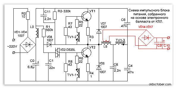
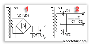
The difference between a CFL circuit and a pulse power supply.
This is one of the most common electrical circuits for energy-saving lamps. To convert a CFL circuit into a switching power supply, you need to install just one jumper between points A – A’ and add a pulse transformer with a rectifier. Elements that can be deleted are marked in red.
And this is a complete circuit of a switching power supply, assembled on the basis of a CFL using an additional pulse transformer.
To simplify, the fluorescent lamp and several parts were removed and replaced with a jumper.
As you can see, the CFL circuit does not require major changes. Additional elements introduced into the scheme are marked in red.
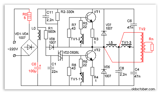
What power power supply can be made from CFLs?
The power of the power supply is limited by the overall power of the pulse transformer, the maximum permissible current of the key transistors and the size of the cooling radiator when using it.
A low-power power supply can be built by winding the secondary winding directly onto the frame of an existing inductor from the lamp block.
If the choke window does not allow winding the secondary winding or if it is necessary to build a power supply with a power significantly exceeding the power of the CFL, then an additional pulse transformer will be needed.
If you need to get a power supply with a power of over 100 Watts, and you are using a ballast from a 20-30 Watt lamp, then, most likely, you will have to make small changes to the electronic ballast circuit.
In particular, you may need to install more powerful diodes VD1-VD4 in the input bridge rectifier and rewind the input inductor L0 with a thicker wire. If the current gain of the transistors turns out to be insufficient, then you will have to increase the base current of the transistors by reducing the values of resistors R5, R6. In addition, you will have to increase the power of resistors in the base and emitter circuits.
If the generation frequency is not very high, then it may be necessary to increase the capacitance of the isolation capacitors C4, C6.
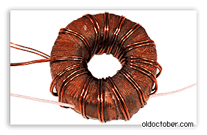
Pulse transformer for power supply.

A feature of half-bridge switching power supplies with self-excitation is the ability to adapt to the parameters of the transformer used. And the fact that the feedback circuit will not pass through our homemade transformer completely simplifies the task of calculating the transformer and setting up the unit. Power supplies assembled according to these schemes forgive errors in calculations of up to 150% or more.
To increase the power of the power supply, we had to wind a TV2 pulse transformer. In addition, I increased the capacitance of the mains voltage filter capacitor C0 to 100µF.
Since the efficiency of the power supply is not 100%, we had to attach some radiators to the transistors.
After all, if the efficiency of the unit is even 90%, you will still have to dissipate 10 Watts of power.
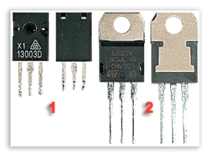
I was unlucky; my electronic ballast was equipped with transistors 13003 pos. 1 of a design that was apparently designed to be attached to a radiator using shaped springs. These transistors do not need gaskets, since they are not equipped with a metal platform, but they also transfer heat much worse. I replaced them with transistors 13007 pos. 2 with holes so that they could be screwed to the radiators with ordinary screws. In addition, 13007 have several times higher maximum permissible currents.
If you wish, you can safely screw both transistors onto one radiator. I checked it works.

Only, the housings of both transistors must be insulated from the radiator housing, even if the radiator is located inside the electronic device housing.
It is convenient to fasten with M2.5 screws, onto which you must first put insulating washers and sections of an insulating tube (cambric). It is allowed to use heat-conducting paste KPT-8, since it does not conduct current.

Attention! Transistors are under mains voltage, so insulating gaskets must ensure electrical safety conditions!
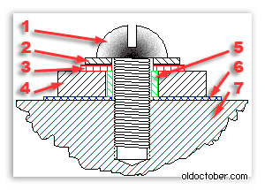
The drawing shows a sectional view of the connection of the transistor to the cooling radiator.
- Screw M2.5.
- Washer M2.5.
- Insulating washer M2.5 – fiberglass, textolite, getinax.
- Transistor housing.
- The gasket is a piece of tube (cambric).
- Gasket – mica, ceramics, fluoroplastic, etc.
- Cooling radiator.

And this is a working 100-watt switching power supply.
The load equivalent resistors are placed in water because their power is insufficient.
The power released at the load is 100 watts.
The frequency of self-oscillations at maximum load is 90 kHz.
The frequency of self-oscillations without load is 28.5 kHz.
Transistor temperature – 75ºC.
The area of the radiators of each transistor is 27 cm².
Throttle temperature TV1 – 45ºC.
TV2 – 2000NM (Ø28 x Ø16 x 9mm)
Rectifier.
All secondary rectifiers of a half-bridge switching power supply must be full-wave. If this condition is not met, the magnetic pipeline may become saturated.
There are two widely used full-wave rectifier designs.
1. Bridge circuit.
2. Circuit with zero point.
The bridge circuit saves a meter of wire, but dissipates twice as much energy on the diodes.
The zero-point circuit is more economical, but requires two perfectly symmetrical secondary windings. Asymmetry in the number of turns or location can lead to saturation of the magnetic circuit.
However, it is precisely zero-point circuits that are used when it is necessary to obtain high currents at a low output voltage. Then, to further minimize losses, instead of conventional silicon diodes, Schottky diodes are used, on which the voltage drop is two to three times less.
Example.
Computer power supply rectifiers are designed according to a zero-point circuit. With a power delivered to the load of 100 Watts and a voltage of 5 Volts, even Schottky diodes can dissipate 8 Watts.
100 / 5 * 0.4 = 8 (Watt)
If you use a bridge rectifier, and even ordinary diodes, then the power dissipated by the diodes can reach 32 Watts or even more.
100 / 5 * 0.8 * 2 = 32 (Watt).
Pay attention to this when you design a power supply so that you don’t have to look for where half the power disappeared.
In low-voltage rectifiers it is better to use a circuit with a zero point. Moreover, with manual winding, you can simply wind the winding in two wires. In addition, high-power pulse diodes are not cheap.
How to properly connect a switching power supply to the network?
To set up switching power supplies, the following connection circuit is usually used. Here, an incandescent lamp is used as a ballast with a nonlinear characteristic and protects the UPS from failure in emergency situations. The lamp power is usually chosen close to the power of the switching power supply being tested.
When the switching power supply is operating at idle or at light load, the resistance of the lamp filament is small and it does not affect the operation of the unit. When, for some reason, the current of the key transistors increases, the lamp coil heats up and its resistance increases, which leads to the current being limited to a safe value.

This drawing shows a diagram of a stand for testing and setting up pulsed power supplies that meets electrical safety standards. The difference between this circuit and the previous one is that it is equipped with an isolation transformer, which provides galvanic isolation of the UPS under study from the lighting network. Switch SA2 allows you to block the lamp when the power supply supplies more power.
And this is an image of a real stand for repairing and setting up switching power supplies, which I made many years ago according to the diagram located above.
An important operation when testing a power supply is testing on an equivalent load. It is convenient to use powerful resistors such as PEV, PPB, PSB, etc. as a load. These “glass-ceramic” resistors are easy to find on the radio market by their green coloring. Red numbers are power dissipation.

It is known from experience that for some reason there is always not enough power equivalent to the load. The resistors listed above can, for a limited time, dissipate power two to three times higher than the rated power. When the power supply is turned on for a long time to check the thermal conditions, and the equivalent load power is insufficient, the resistors can simply be lowered into water.
Be careful, beware of burns!
Load resistors of this type can heat up to temperatures of several hundred degrees without any external manifestations!
That is, you will not notice any smoke or change in color and you can try to touch the resistor with your fingers.
How to set up a switching power supply?
Actually, a power supply assembled on the basis of a working electronic ballast does not require any special adjustment.
It needs to be connected to the load equivalent and make sure that the power supply is capable of delivering the calculated power.
During a run under maximum load, you need to monitor the dynamics of the temperature rise of the transistors and transformer. If the transformer heats up too much, then you need to either increase the cross-section of the wire, or increase the overall power of the magnetic circuit, or both.
If the transistors get very hot, you need to install them on radiators.
If a home-wound inductor from a CFL is used as a pulse transformer, and its temperature exceeds 60... 65ºС, then the load power must be reduced.
It is not recommended to raise the temperature of the transformer above 60... 65ºС, and of transistors above 80... 85ºС.
What is the purpose of the switching power supply circuit elements?
R0 – limits the peak current flowing through the rectifier diodes at the moment of switching on. In CFLs it also often serves as a fuse.
VD1… VD4 – bridge rectifier.
L0, C0 – power filter.
R1, C1, VD2, VD8 – converter starting circuit.
The launch node works as follows. Capacitor C1 is charged from the source through resistor R1. When the voltage on capacitor C1 reaches the breakdown voltage of dinistor VD2, the dinistor unlocks itself and unlocks transistor VT2, causing self-oscillations. After generation occurs, rectangular pulses are applied to the cathode of the diode VD8 and the negative potential reliably locks the dinistor VD2.
R2, C11, C8 – make it easier to start the converter.
R7, R8 – improve transistor blocking.
R5, R6 – limit the base current of the transistors.
R3, R4 – prevent saturation of transistors and act as fuses in case of breakdown of transistors.
VD7, VD6 – protect transistors from reverse voltage.
TV1 – feedback transformer.
L5 – ballast choke.
C4, C6 are decoupling capacitors on which the supply voltage is divided in half.
TV2 – pulse transformer.
VD14, VD15 – pulse diodes.
C9, C10 – filter capacitors.