Do-it-yourself class A transistor amplifier. Datagor Practical Electronics Magazine Economical low-frequency amplifiers using transistors
After mastering the basics of electronics, the novice radio amateur is ready to solder his first electronic designs. Audio power amplifiers are typically the most repeatable designs. There are quite a lot of schemes, each with its own parameters and design. This article will discuss several simple and fully working amplifier circuits that can be successfully repeated by any radio amateur. The article does not use complex terms and calculations; everything is simplified as much as possible so that no additional questions arise.
Let's start with a more powerful circuit.
So, the first circuit is made on the well-known TDA2003 microcircuit. This is a mono amplifier with an output power of up to 7 watts into a 4 ohm load. I want to say that the standard circuit for connecting this microcircuit contains a small number of components, but a couple of years ago I came up with a different circuit on this microcircuit. In this circuit, the number of components is reduced to a minimum, but the amplifier has not lost its sound parameters. After developing this circuit, I began making all my amplifiers for low-power speakers using this circuit.
The circuit of the presented amplifier has a wide range of reproducible frequencies, a supply voltage range from 4.5 to 18 volts (typical 12-14 volts). The microcircuit is installed on a small heat sink, since the maximum power reaches up to 10 Watts.
The microcircuit is capable of operating at a load of 2 ohms, which means that 2 heads with a resistance of 4 ohms can be connected to the amplifier output.
The input capacitor can be replaced with any other one, with a capacity from 0.01 to 4.7 μF (preferably from 0.1 to 0.47 μF), you can use both film and ceramic capacitors. It is advisable not to replace all other components.

Volume control from 10 to 47 kOhm.
The output power of the microcircuit allows it to be used in low-power speakers for PCs. It is very convenient to use the chip for stand-alone speakers for a mobile phone, etc.
The amplifier works immediately after switching on and does not require additional adjustment. It is recommended to additionally connect the power supply minus to the heat sink. It is advisable to use all electrolytic capacitors at 25 Volts.
The second circuit is assembled using low-power transistors and is more suitable as a headphone amplifier.

This is probably the highest quality circuit of its kind, the sound is clear, you can feel the entire frequency spectrum. With good headphones, it feels like you have a full-fledged subwoofer.

The amplifier is assembled with only 3 reverse conduction transistors; as the cheapest option, transistors of the KT315 series were used, but their choice is quite wide.
The amplifier can operate at a low-impedance load, up to 4 ohms, which makes it possible to use the circuit to amplify the signal of a player, radio, etc. A 9-volt Krona battery is used as a power source.
The final stage also uses KT315 transistors. To increase the output power, you can use KT815 transistors, but then you will have to increase the supply voltage to 12 volts. In this case, the amplifier power will reach up to 1 Watt. The output capacitor can have a capacity from 220 to 2200 µF.
The transistors in this circuit do not heat up, therefore, no cooling is needed. If you use larger output transistors, you may need small heat sinks for each transistor.
And finally - the third scheme. An equally simple, but proven version of the amplifier structure is presented. The amplifier is capable of operating from reduced voltage to 5 volts, in which case the PA output power will be no more than 0.5 W, and the maximum power with a 12 volt supply reaches up to 2 Watts.

The output stage of the amplifier is built on a domestic complementary pair. The amplifier is regulated by selecting resistor R2. To do this, it is advisable to use a 1 kOhm trimmer. Slowly rotate the regulator until the quiescent current of the output stage is 2-5 mA.
The amplifier does not have high input sensitivity, so it is advisable to use a pre-amplifier before the input.

The diode plays a significant role in the circuit; it is here to stabilize the mode of the output stage.
The output stage transistors can be replaced with any complementary pair of corresponding parameters, for example KT816/817. The amplifier can power low-power stand-alone speakers with a load resistance of 6-8 ohms.
List of radioelements
| Designation | Type | Denomination | Quantity | Note | Shop | My notepad | |
|---|---|---|---|---|---|---|---|
| Amplifier on TDA2003 chip | |||||||
| Audio amplifier | TDA2003 | 1 | To notepad | ||||
| C1 | 47 uF x 25V | 1 | To notepad | ||||
| C2 | Capacitor | 100 nF | 1 | Film | To notepad | ||
| C3 | Electrolytic capacitor | 1 uF x 25V | 1 | To notepad | |||
| C5 | Electrolytic capacitor | 470 uF x 16V | 1 | To notepad | |||
| R1 | Resistor | 100 Ohm | 1 | To notepad | |||
| R2 | Variable resistor | 50 kOhm | 1 | From 10 kOhm to 50 kOhm | To notepad | ||
| Ls1 | Dynamic head | 2-4 Ohm | 1 | To notepad | |||
| Transistor amplifier circuit No. 2 | |||||||
| VT1-VT3 | Bipolar transistor | KT315A | 3 | To notepad | |||
| C1 | Electrolytic capacitor | 1 uF x 16V | 1 | To notepad | |||
| C2, C3 | Electrolytic capacitor | 1000 uF x 16V | 2 | To notepad | |||
| R1, R2 | Resistor | 100 kOhm | 2 | To notepad | |||
| R3 | Resistor | 47 kOhm | 1 | To notepad | |||
| R4 | Resistor | 1 kOhm | 1 | To notepad | |||
| R5 | Variable resistor | 50 kOhm | 1 | To notepad | |||
| R6 | Resistor | 3 kOhm | 1 | To notepad | |||
| Dynamic head | 2-4 Ohm | 1 | To notepad | ||||
| Transistor amplifier circuit No. 3 | |||||||
| VT2 | Bipolar transistor | KT315A | 1 | To notepad | |||
| VT3 | Bipolar transistor | KT361A | 1 | To notepad | |||
| VT4 | Bipolar transistor | KT815A | 1 | To notepad | |||
| VT5 | Bipolar transistor | KT816A | 1 | To notepad | |||
| VD1 | Diode | D18 | 1 | Or any low power | To notepad | ||
| C1, C2, C5 | Electrolytic capacitor | 10 uF x 16V | 3 | ||||
The amplifier is capable of delivering 2kW peak power, and 1.5kW continuous, which means this amplifier is capable of burning out most speakers you know. To imagine such power in action, you can connect (which I strongly advise against doing) two 8-ohm speakers connected in series to a 220V AC network. In this case, one speaker will have 110V effective voltage at a load of 8 ohms - 1,500W. How long do you think the acoustics will work in this mode? If you still have the desire to work on this amplifier, move on...
Amplifier Description
First, let's look at the requirements to achieve 1.5kW into 4 ohms. We need 77.5V rms voltage, but we must have some margin because the supply voltage will drop under load and there will always be some voltage drop across the collector-emitter junctions and emitter resistors.
So the supply voltage should be...
VDC = VRMS * 1.414
VDC = 77.5 * 1.414 = ±109.6V DC voltage
Since we haven't taken losses into account, we need to add about 3-5V for the amplifier tip, and an additional 10V for supply voltage drop under full load.
A 2 x 90V transformer will produce a no-load voltage of ±130V (260V between the ends of the rectifier), so the power supply must be handled with extreme care
Bipolar transistors were selected as the most suitable for the final stage of the amplifier. This is primarily dictated by the supply voltage, which exceeds the limit voltage for most MOSFET transistors. This is also a lot for bipolar transistors, but MJ15004/5 or MJ21193/4 meet the maximum voltage requirement, which means we will focus on them.
P=V? / R = 65 ? / 4 = 1056W
That is, equal to the average electric heater...
Remember that when driving a resistive load with 45° phase shifts, the power dissipation almost doubles. Based on this, it follows that good cooling is vital for this amplifier. You will need good radiators and fans for forced cooling (natural convection will not help).
MJ15024/5 (or MJ21193/4) transistors in a K-3 package (iron with two terminals like KT825/827), and are designed to dissipate 250W at a temperature of 25°C. The K-3 transistor package was chosen because it has the highest power dissipation rating because the thermal resistance is lower than any other plastic packaged transistor.
MJE340/350 in the voltage amplifier stage guarantees good linearity. But even with a current through the stage of 12mA, the power is 0.72W, so Q4, Q6, Q9 and Q10 must have heat sinks. The transistor (Q5), which determines the bias of the final stage, must be installed on a common radiator with the terminal and have reliable thermal contact.
The short circuit protection circuit (Q7, Q8) limits the current to 12A and the power released by one transistor to about 175W, while long-term operation of the amplifier in this mode is not permissible.
1500W professional amplifier circuit.
Additional feedback elements (R6a and C3a, shown dotted) are optional. They may be necessary if self-excitation of the amplifier occurs. Reverse diodes (D9 and D10) protect the amplifier transistors from back EMF when operating an active load. 1N5404 series diodes can withstand peak current up to 200A. The rated voltage must be at least 400V.
Resistor VR1 100 ohm is used to balance the amplifier for DC current. With the component ratings shown in the diagram, the initial offset should be within ±25mV before tuning. Resistor VR2 is used to set the quiescent current of the final stage. The quiescent current is adjusted by measuring the voltage across resistor R19 or R20, which should be within 150mV.
Input stage sensitivity is 1.77V for 900W at 8 ohms, or 1800W at 4 ohms.
Power supply:
The power supply required for the amplifier requires a serious design approach. Firstly, you need a step-down transformer with a power of at least 2kW. Power filter capacitors must be rated at 150V and can withstand up to 10A ripple current. Capacitors that do not meet these requirements may simply explode when the amplifier is operating at full power.
An important detail is the bridge rectifier. Although 35A bridges seem to be able to cope with the task, the peak repeating current exceeds the bridges' ratings. I recommend using two bridges connected in parallel as shown in the diagram. The rated voltage of the bridge rectifier must be a minimum of 400V, and they must be mounted on a sufficient heat sink for cooling.
Power supply circuit for a 1500W amplifier.
The diagram shows capacitors made up of four low-voltage capacitors since they are easier to find, and the rectifier also consists of two bridges connected in parallel.
Additional voltage sources of 5V can be eliminated, while the peak power will decrease from 2048W to 1920W, which is not significant.
The P39 module is a soft start system and consists of a relay, parallel to the contacts of which resistors with a total power of 150W and a resulting resistance of 33 Ohms are connected.
There were already publications on Habré about DIY tube amplifiers, which were very interesting to read. There is no doubt that their sound is wonderful, but for everyday use it is easier to use a device with transistors. Transistors are more convenient because they do not require warming up before operation and are more durable. And not everyone will risk starting a tube saga with anode potentials of 400 V, but transistor transformers of a couple of tens of volts are much safer and simply more accessible.
As a circuit for reproduction, I chose a circuit from John Linsley Hood from 1969, taking the author’s parameters based on the impedance of my 8 Ohm speakers.
The classic circuit from a British engineer, published almost 50 years ago, is still one of the most reproducible and receives extremely positive reviews. There are many explanations for this:
- the minimum number of elements simplifies installation. It is also believed that the simpler the design, the better the sound;
- despite the fact that there are two output transistors, they do not need to be sorted into complementary pairs;
- an output of 10 Watts is sufficient for ordinary human dwellings, and an input sensitivity of 0.5-1 Volts agrees very well with the output of most sound cards or players;
- class A - it is also class A in Africa, if we are talking about good sound. Comparison with other classes will be discussed below. 
Interior design
An amplifier starts with power. It is best to separate two channels for stereo using two different transformers, but I limited myself to one transformer with two secondary windings. After these windings, each channel exists on its own, so we must not forget to multiply by two everything mentioned below. On a breadboard we make bridges using Schottky diodes for the rectifier.
It is possible with ordinary diodes or even ready-made bridges, but then they need to be bypassed with capacitors, and the voltage drop across them is greater. After the bridges there are CRC filters consisting of two 33,000 uF capacitors and a 0.75 Ohm resistor between them. If you take a smaller capacitance and a resistor, the CRC filter will become cheaper and heat up less, but the ripple will increase, which is not comme il faut. These parameters, IMHO, are reasonable from a price-effect point of view. A powerful cement resistor is needed for the filter; at a quiescent current of up to 2A, it will dissipate 3 W of heat, so it is better to take it with a margin of 5-10 W. For the remaining resistors in the circuit, 2 W of power will be quite enough.
Next we move on to the amplifier board itself. Online stores sell a lot of ready-made kits, but there are no fewer complaints about the quality of Chinese components or illiterate layouts on boards. Therefore, it is better to do it yourself, at your own discretion. I made both channels on a single breadboard so that I could later attach it to the bottom of the case. Running with test elements:

Everything except the output transistors Tr1/Tr2 is on the board itself. The output transistors are mounted on radiators, more on that below. The following remarks should be made to the author’s diagram from the original article:
Not everything needs to be soldered tightly at once. It is better to first set up resistors R1, R2 and R6 as trimmers, unsolder them after all adjustments, measure their resistance and solder the final constant resistors with the same resistance. The setup comes down to the following operations. First, using R6, it is set so that the voltage between X and zero is exactly half of the voltage +V and zero. In one of the channels I didn’t have enough 100 kOhm, so it’s better to take these trimmers with a reserve. Then, using R1 and R2 (maintaining their approximate ratio!) the quiescent current is set - we set the tester to measure direct current and measure this very current at the positive input point of the power supply. I had to significantly reduce the resistance of both resistors to obtain the required quiescent current. The quiescent current of an amplifier in class A is maximum and, in fact, in the absence of an input signal, all of it goes into thermal energy. For 8-ohm speakers, this current, according to the author's recommendation, should be 1.2 A at a voltage of 27 Volts, which means 32.4 Watts of heat per channel. Since setting the current can take several minutes, the output transistors must already be on cooling radiators, otherwise they will quickly overheat and die. Because they are mostly heated.
It is possible that, as an experiment, you will want to compare the sound of different transistors, so you can also leave the possibility of convenient replacement for them. I tried 2N3906, KT361 and BC557C at the input, there was a slight difference in favor of the latter. In the pre-weekend we tried KT630, BD139 and KT801, and settled on imported ones. Although all of the above transistors are very good, the difference may be rather subjective. At the output, I immediately installed 2N3055 (ST Microelectronics), since many people like them.
When adjusting and lowering the resistance of the amplifier, the low-frequency cutoff frequency may increase, so for the input capacitor it is better to use not 0.5 µF, but 1 or even 2 µF in a polymer film. There is still a Russian picture-scheme of an “Ultralinear Class A Amplifier” floating around the Internet, where this capacitor is generally proposed as 0.1 uF, which is fraught with a cutoff of all bass at 90 Hz:

They write that this circuit is not prone to self-excitation, but just in case, a Zobel circuit is placed between point X and ground: R 10 Ohm + C 0.1 μF.
- fuses, they can and should be installed both on the transformer and on the power input of the circuit.
- it would be very appropriate to use thermal paste for maximum contact between the transistor and the heatsink.
Metalworking and carpentry
Now about the traditionally most difficult part in DIY - the body. The dimensions of the case are determined by radiators, and in class A they must be large, remember about 30 watts of heat on each side. At first, I underestimated this power and made a case with average radiators of 800 cm² per channel. However, with the quiescent current set to 1.2A, they heated up to 100°C in just 5 minutes, and it became clear that something more powerful was needed. That is, you need to either install larger radiators or use coolers. I didn’t want to make a quadcopter, so I bought giant, handsome HS 135-250 with an area of 2500 cm² for each transistor. As practice has shown, this measure turned out to be a little excessive, but now the amplifier can be easily touched with your hands - the temperature is only 40°C even in rest mode. Drilling holes in the radiators for mounts and transistors became a bit of a problem - the initially purchased Chinese metal drills were drilled extremely slowly, each hole would have taken at least half an hour. Cobalt drills with a sharpening angle of 135° from a well-known German manufacturer came to the rescue - each hole is passed in a few seconds!I made the body itself from plexiglass. We immediately order cut rectangles from glaziers, make the necessary holes for fastenings in them and paint them on the reverse side with black paint.


The plexiglass painted on the reverse side looks very beautiful. Now all that remains is to assemble everything and enjoy the music... oh yes, during final assembly it is also important to properly distribute the ground to minimize the background. As was discovered decades before us, C3 must be connected to the signal ground, i.e. to the minus of the input-input, and all other minuses can be sent to the “star” near the filter capacitors. If everything is done correctly, then you will not be able to hear any background, even if you bring your ear to the speaker at maximum volume. Another “ground” feature that is typical for sound cards that are not galvanically isolated from the computer is interference from the motherboard, which can get through USB and RCA. Judging by the Internet, the problem occurs frequently: in the speakers you can hear the sounds of the HDD, printer, mouse and the background power supply of the system unit. In this case, the easiest way to break the ground loop is to cover the ground connection on the amplifier plug with electrical tape. There is nothing to fear here, because... There will be a second ground loop through the computer.
I didn’t make a volume control on the amplifier, because I couldn’t get any high-quality ALPS, and I didn’t like the rustling of Chinese potentiometers. Instead, a regular 47 kOhm resistor was installed between ground and the input signal. Moreover, the regulator on an external sound card is always at hand, and every program also has a slider. Only the vinyl player does not have a volume control, so to listen to it I attached an external potentiometer to the connecting cable.

I can guess this container in 5 seconds...
Finally, you can start listening. The sound source is Foobar2000 → ASIO → external Asus Xonar U7. Microlab Pro3 speakers. The main advantage of these speakers is a separate block of its own amplifier on the LM4766 chip, which can be immediately removed somewhere away. An amplifier from a Panasonic mini-system with a proud Hi-Fi inscription or an amplifier from the Soviet Vega-109 player sounded much more interesting with this acoustics. Both of the above devices operate in class AB. JLH, presented in the article, beat all the above-mentioned comrades by one wicket, according to the results of a blind test for 3 people. Although the difference was audible to the naked ear and without any tests, the sound was clearly more detailed and transparent. It's quite easy, for example, to hear the difference between MP3 256kbps and FLAC. I used to think that the lossless effect was more like a placebo, but now my opinion has changed. Likewise, it has become much more pleasant to listen to files uncompressed from loudness war - dynamic range less than 5 dB is not ice at all. Linsley-Hood is worth the investment of time and money, because a similar brand amp will cost much more.Material costs
Transformer 2200 rub.Output transistors (6 pcs. with a reserve) 900 rub.
Filter capacitors (4 pcs) 2700 rub.
“Rassypukha” (resistors, small capacitors and transistors, diodes) ~ 2000 rub.
Radiators 1800 rub.
Plexiglas 650 rub.
Paint 250 rub.
Connectors 600 rub.
Boards, wires, silver solder, etc. ~1000 rub.
TOTAL ~12100 rub.
Nikolay Troshin
A simple germanium power amplifier.
Recently, there has been a noticeable increase in interest in power amplifiers based on germanium transistors. There is an opinion that the sound of such amplifiers is softer, reminiscent of “tube sound”.
I bring to your attention two simple circuits of low-frequency power amplifiers using germanium transistors, which I tested some time ago.
More modern circuit solutions are used here than those used in the 70s, when “germanium” was in use. This made it possible to obtain decent power with good sound quality.
The circuit in the figure below is a reworked version of the low-frequency amplifier for “germanium” from my article in Radio magazine No. 8, 1989 (pp. 51-55).
The output power of this amplifier is 30 W with a speaker load impedance of 4 ohms, and approximately 18 W with a load impedance of 8 ohms.
The amplifier supply voltage (U supply) is bipolar ±25 V;
A few words about the details:
When assembling an amplifier, it is advisable to use mica capacitors as constant capacitors (in addition to electrolytic ones). For example, the CSR type, such as below in the figure.

MP40A transistors can be replaced with MP21, MP25, MP26 transistors. Transistors GT402G - on GT402V; GT404G - to GT404V;
The GT806 output transistors can be assigned any letter indices. I do not recommend using lower-frequency transistors such as P210, P216, P217 in this circuit, since at frequencies above 10 kHz they work rather poorly here (distortion is noticeable), apparently due to a lack of current amplification at high frequencies.
The area of radiators for output transistors must be at least 200 cm2, for pre-terminal transistors - at least 10 cm2.
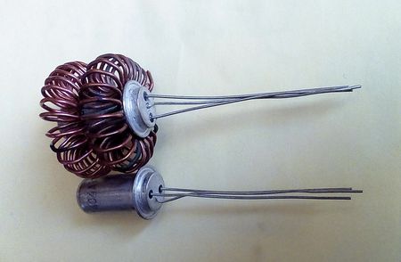
For transistors of the GT402 type, it is convenient to make radiators from a copper (brass) or aluminum plate, 0.5 mm thick, 44x26.5 mm in size.

The plate is cut along the lines, then this workpiece is shaped into a tube, using for this purpose any suitable cylindrical mandrel (for example, a drill).
After this, the workpiece (1) is tightly placed on the transistor body (2) and pressed with a spring ring (3), having previously bent the side mounting ears.
The ring is made of steel wire with a diameter of 0.5-1.0 mm. Instead of a ring, you can use a copper wire bandage.
Now all that remains is to bend the side ears from below to attach the radiator to the transistor body and bend the cut feathers to the desired angle.
A similar radiator can also be made from a copper tube with a diameter of 8 mm. Cut a piece of 6...7 cm, cut the tube along the entire length on one side. Next, we cut the tube into 4 parts half the length and bend these parts in the form of petals and place them tightly on the transistor.
Since the diameter of the transistor body is about 8.2 mm, due to the slot along the entire length of the tube, it will fit tightly onto the transistor and will be held on its body due to its springy properties.
Resistors in the emitters of the output stage are either wirewound with a power of 5 W, or type MLT-2 3 Ohm, 3 pieces in parallel. I do not recommend using imported films - they burn out instantly and imperceptibly, which leads to the failure of several transistors at once.
Setting:
Setting up an amplifier correctly assembled from serviceable elements comes down to setting the quiescent current of the output stage to 100 mA using a trimming resistor (it is convenient to control the 1 Ohm emitter resistor - voltage 100 mV).
It is advisable to glue or press the VD1 diode to the heatsink of the output transistor, which promotes better thermal stabilization. However, if this is not done, the quiescent current of the output stage from cold 100mA to hot 300mA changes, in general, not catastrophically.
Important: Before turning on for the first time, you must set the trimming resistor to zero resistance.
After tuning, it is advisable to remove the trimming resistor from the circuit, measure its real resistance and replace it with a constant one.
The most scarce part for assembling an amplifier according to the above diagram is the GT806 output germanium transistors. Even in the bright Soviet times it was not so easy to acquire them, and now it is probably even more difficult. It is much easier to find germanium transistors of types P213-P217, P210.
If for some reason you cannot purchase GT806 transistors, then we offer you another amplifier circuit, where you can use the aforementioned P213-P217, P210 as output transistors.
This scheme is a modernization of the first scheme. The output power of this amplifier is 50W into a 4-ohm load and 30W into an 8-ohm load.
The supply voltage of this amplifier (U supply) is also bipolar and is ±27 V;
Operating frequency range 20Hz…20kHz:
What changes have been made to this scheme;
Added two current sources to the “voltage amplifier” and another stage to the “current amplifier”.
The use of another amplification stage on fairly high-frequency P605 transistors made it possible to somewhat unload the GT402-GT404 transistors and boost the very slow P210.
It turned out pretty good. With an input signal of 20 kHz, and with an output power of 50 W, distortion at the load is practically not noticeable (on the oscilloscope screen).
Minimal, barely noticeable distortions of the output signal shape with P210 type transistors occur only at frequencies of about 20 kHz at a power of 50 watts. At frequencies below 20 kHz and powers below 50 W, distortion is not noticeable.
In a real music signal, such powers at such high frequencies usually do not exist, so I did not notice any differences in the sound (by ear) of an amplifier with GT806 transistors and P210 transistors.
However, with transistors like GT806, if you look at it with an oscilloscope, the amplifier still works better.
With an 8 Ohm load in this amplifier, it is also possible to use output transistors P216...P217, and even P213...P215. In the latter case, the amplifier supply voltage will need to be reduced to ±23V. The output power will, of course, also drop.
Increasing the power supply leads to an increase in output power, and I think that the amplifier circuit in the second option has such potential (reserve), however, I did not tempt fate with experiments.
The following radiators are required for this amplifier - for output transistors with a dissipation area of at least 300 cm2, for pre-output P605 - at least 30 cm2, and even for GT402, GT404 (with a load resistance of 4 Ohms) are also needed.
For transistors GT402-404, you can do it easier;
Take copper wire (without insulation) with a diameter of 0.5-0.8, wind the wire turn to turn on a round mandrel (4-6 mm in diameter), bend the resulting winding into a ring (with an internal diameter less than the diameter of the transistor body), connect the ends by soldering and put the resulting “donut” on the transistor body.
It will be more efficient to wind the wire not on a round, but on a rectangular mandrel, since this increases the area of contact of the wire with the transistor body and, accordingly, increases the efficiency of heat removal.
Also, to increase the efficiency of heat removal for the entire amplifier, you can reduce the area of the radiators and use a 12V cooler from the computer for cooling, powering it with a voltage of 7...8V.
Transistors P605 can be replaced with P601...P609.
The setup of the second amplifier is similar to that described for the first circuit.
A few words about acoustic systems. It is clear that to obtain good sound they must have the appropriate power. It is also advisable, using a sound generator, to go through the entire frequency range at different powers. The sound should be clear, without wheezing or rattling. Especially, as my experience has shown, this is especially true for the high-frequency speakers of speakers like S-90.
If anyone has any questions about the design and assembly of amplifiers, ask, I will try to answer if possible.
Good luck to all of you in your creativity and all the best!
- 28.09.2014
After closing the car door with the engine not running, such a retarder will not turn off the light immediately, but after 10-15 seconds. In this case, when the engine is running, the retarder will not have to work. In terms of power supply, the circuit is connected in parallel to the lighting lamp L1. Relay contacts K1 block the lighting switch P1. when the engine is not running when the door is opened...
- 06.07.2015
Using the NCP2809 chip, you can assemble a high-quality AF power amplifier for headphones. Amplifier output power 135 mW (16 Ohms) per channel. The microcircuit is characterized by a low supply voltage from 2.2V to 5.5V, and the microcircuit can also be connected directly to the battery without a voltage stabilizer. An output power of 135mW is achieved with a supply voltage of 5V at the load...
- 04.11.2014
The stereo amplifier is designed for a small speaker. It is made on KA2206 and develops a power of 3 W per channel with a load resistance of 4 Ohms, when powered by a constant voltage from 15 to 24 V. Amplifier current consumption is no more than 300mA. The KA2206 microcircuit is connected according to a standard circuit. A signal from the telephone output of the CD-ROM is supplied to its input. ...
- 28.09.2014
The basis of the frequency meter is IC K155LA3, the frequency meter consists of an input device, a Schmitt trigger, a differentiating circuit, a waiting multivibrator and a measuring device. The input device is made on VT1 connected according to the emitter follower circuit. VD1 VD2 protect the frequency meter from overloads. From the input device, the signal is fed to the Schmitt trigger (DD1.1 DD1.2). Next, the formed rectangular pulses through the differentiating...